Contents
Installation
After install the OptFlux, the Reg4OptFlux plugin can be installed through the repository manager present in OptFlux.
- You can access the Repository option under the Help -> Repository Manager menu.

- After accessing to the Repository Manager click over the Regulatory Tool (version x) and perform the installation by clicking on Install - Version x.x.x).
- Click on Restart button.
Example file
You can download it here -> IntegratedModelToy

This tutorial uses an example based on work presented by J. Kim and J. Reed.OptORF: Optimal metabolic and regulatory perturbations for metabolic engineering of microbial strains. BMC, 2010
- The regulatory model is composed by a transcription factor (TF1) that is activated when metabolite S is present, activates the expression of two genes (G3, G5) and represses the expression of gene G1A.
- The Gene Reactions rules are characterized in the following way: R1 is catalyzed when the gene G1A and G1B are activated; R2 is catalyzed by the gene G2; R3 and R4 are catalyzed by the genes G3 and G4, respectively; finally, R5 can be catalyzed by either genes G5 or G6.
- At the metabolic level, the substrate (S) is utilized to produce biomass (B) and by-products P1 and P2. The cellular objective is to maximize biomass production (B) and the engineering objective is the production of P1. Reaction R2 converts the internal metabolite I1 into product P1 and 0.08 biomass (B), whereas reaction R5 converts the internal metabolite I2 into product P2 and 0.12 Biomass. The stoichiometric coefficients of all other reactions reflect a one-to-one relationship between molecule quantities.
Define a regulatory model file to be used in the Reg4OptFlux plugin
Reg4OptFlux plugin supports the loading of a regulatory model in excel file format (.xls and .xlsx) or the comma-separated values file format (.csv).
- Is possible to define a regulatory model by describing only the genes that have an associated regulatory rule, or a regulatory model containing all the genes that are present in the metabolic model and the regulatory model.
In the implementation of the regulatory model is mandatory the description of the following elements:
1. A column containing the identifiers for each gene
- The gene identifier must be the same that is used in the metabolic GPRs rules, to link a metabolic gene to a regulatory rule.
Example: if you have a reaction R1 that have two associated genes b0536 and b2567 and they are affected by a regulatory rule, you must define a column containing the identifiers (b0536 and b2567) of these two genes.
2. A column with the identifiers that will map a rule to the other rules
If you have three regulatory genes and do you want to associate them by the respective regulatory rule identifiers, you have to define these associations as shown in the following example:
    rule identifiers   regulatory rules
        tf1             R_Substrate>0
        tf2             NOT tf1
        tf3             tf4 OR NOT tf2
As shown in the previous example the rule identifier must be the same that is used in the regulatory rule, thus, the tf2 regulatory rule is linked to the tf1 regulatory rule by the tf1 identifier, and the tf3 regulatory rule is linked to tf2 regulatory rule by the tf2 identifier. Is advisable to use the names of the transcriptional factors to perform these associations.
3. A column describing the regulatory rules for each gene
- The regulatory rules must be defined in the last column of your regulatory file.
A column describing the name for each one of the genes that are present in the regulatory model can be also defined (this is an optional feature)
Examples
The following figure shows a regulatory model in an excel file format containing only the genes with an associated regulatory rule. The first column contains the gene identifiers, the second column contains the gene names (optional), the third column contains the rule identifiers and the last column contains the regulatory rules.

The next figure, shows a regulatory model in a comma-separated values file format containing all genes (includes also all metabolic genes). However, the name of the genes are not described in the regulatory file.

Note: If the regulatory model contains any rule with external stimuli, such as lys-L(e)>0, leu-L(e)>0, etc..., these elements must have the same identifier of the drain reactions (the drain reaction ID) of the metabolic model.
Build a new project containing an integrated model
User can build a project with an integrated model in two distinctive ways:
1. Through the "New Project Wizard Operation"

- Step 1
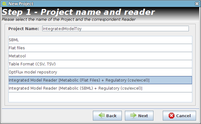
Create an integrated model project using a metabolic model in flat files format and a regulatory model in excel or csv format.
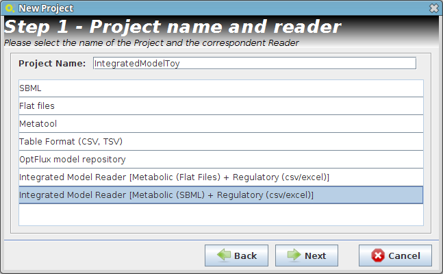
Create an integrated model project using a metabolic model in SBML file format and a regulatory model in excel or csv format.


- Step 2
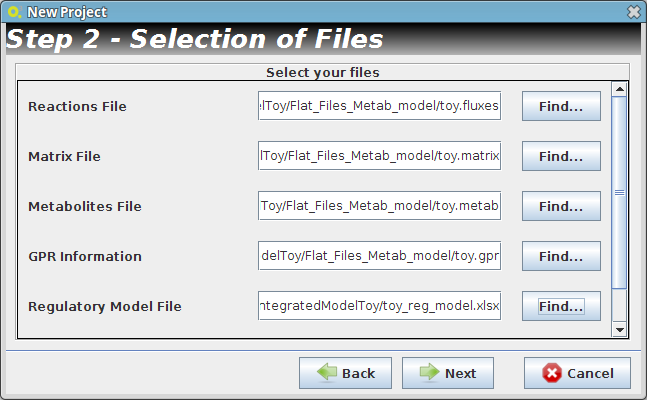
Select the metabolic model flat files and the regulatory model in excel or csv format.
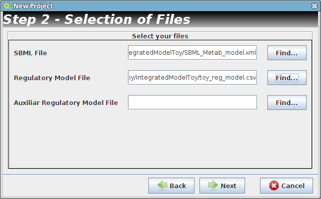
Select the metabolic model SBML file and the regulatory model in excel or csv format.


- Reader Configuration
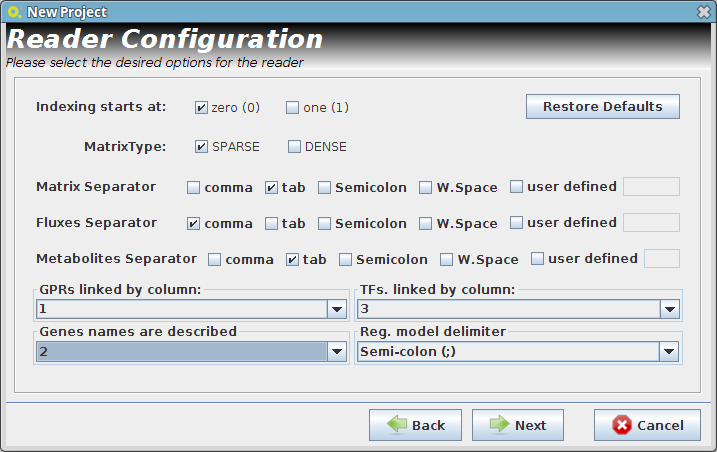
Select the respective columns according your regulatory model configuration, and select the delimiters that you are using on your Flat Files.
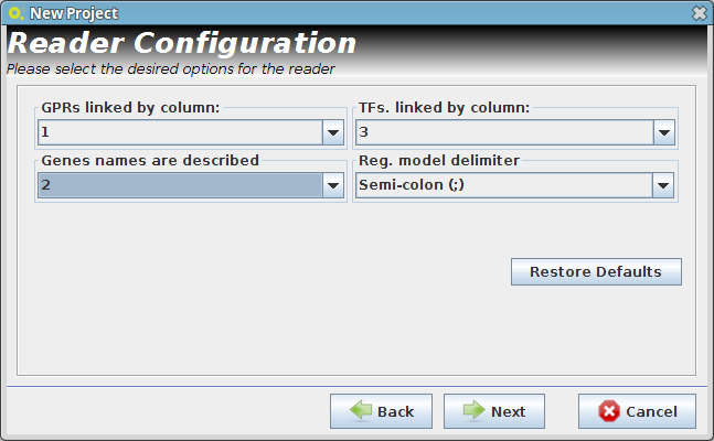
Select the respective columns according your regulatory model configuration.


In this step some definitions can be selected (depending from the type of the delimiters that are used on user Flat Files)
Continue to next panel Step 3 by pressing next. The user can select any of the options presented in the panel Step 3 or continue to next panel Step 4.
- Step 4

After selecting the biomass reaction, press the Finish button and a new project will be created. The model components will be displayed on Clipboard panel at left.

2. From an existing project
To create an integrated model project by this way it's required to have a metabolic model project already loaded (for more information click here). It's mandatory that the previous loaded metabolic model, have the GPR Rules information.

- The following dialog panel will be displayed

1. Project
You can select the model/project to integrate the regulatory model.
2. Select Regulatory Model File
You can select the regulatory model file in excel or csv file format
3. Select Auxiliar Model File
You can select an auxiliary file to the regulatory model, where are described the type (condition or transcritional factor) of identifiers that the plugin is not be able to perform the automatic detection of its type. These are shown in a specific panel, when the regulatory model is loaded and they can be saved as an "auxiliar model file" for future use.
4. Select the respective columns according your regulatory model configuration
After pressing the Ok button the new project will be created, and the model components will be displayed on Clipboard.
How to perform a mutant simulation
- You can access the Simulation option under the Simulation->Regulatory menu or right clicking on the Integrated Model icon on the clipboard.

- In both simulation types you can select the project to work, and set up your configuration.
Regulatory Model Simulation

1. Select genes to knockout
Selecting in the Gene list you can add/remove (using the arrows buttons) genes to the knockout list (the list of genes to be knocked out, in the right).
Genes can be displayed by Name or ID.
2. Variables
Here you can define which variables (present in metabolic model or regulatory model) are to be considered in the simulation of the regulatory network.
3. Simulation Method
Methods to perform the regulatory network simulation. In future new methods will be added.
4. First Step Boolean Simulation
This parameter is related to BRNV simulation method (define how genes are knockout at beginning of regulatory simulation) , for example the user can assign a initial set of knockout genes instead of using the predefined OptFlux Strategy.
- And that's all!! You can press OK and the results will be loaded into the clipboard.
Integrated Model Simulation

1. Select genes to knockout
Selecting in the Gene list you can add/remove (using the arrows buttons) genes to the knockout list (the list of genes to be knocked out, in the right).
2. Select Environmental Conditions
If you have created environmental conditions you can select them to be used as constraints in the simulation. These can be used to define the values of drain fluxes, i.e. the rates at which metabolites are consumed or produced.
3. Objective Function Definition
Here you can select the reaction to optimize (biomass, by default), and you can also define if you will be maximizing or minimizing that flux.
4. Set Regulatory Variables
Here you can define the value of all regulatory user variables, and see the values of the model variables.
5. Select Simulation Method
OptFlux can use several simulation methods for knockout simulations, namely:
SR-FBA and Integrated_BRN plus: FBA or pFBA or MOMA
- And that's all!! You can press OK and the results will be loaded into the clipboard.

Critical Genes
The regulatory plug-in allows the users to define which are the genes present on the integrated model that are essential for the strain to survive, i.e. to keep a value of growth (biomass reaction flux) different from zero. The essential genes can be calculated using the simulation algorithms presented in the regulatory plugin. Also, the software allows the user to load these genes or reactions from a file (if they are available). The list of essential genes can be manually edited, allowing users to add or remove elements, given their knowledge or the purpose of their experiments.
How to do load critical genes from a file
- To load the information from a file just access the Load Critical Regulatory Genes option under the Import->Load Critical Regulatory Genes menu in the Project Menu or right click on the Integrated Model icon in the clipboard.

- The following dialog will be displayed.

1. Select Project
You can select a project to assign the set of critical regulatory genes.
2. Select File
You can select the file that have the critical genes information.
- Now press OK and you can see a new element on the clipboard with the loaded critical genes.

How to determining essential genes
- You can access the Compute Critical Regulatory Genes option under the Analysis->Regulatory->Compute Critical Regulatory Genes menu or by right clicking on the Integrated Model icon on the clipboard.


1. Select Project
You can select a project to assign the set of critical regulatory genes.
2. Set Regulatory User Variables
Here you can define the value of all regulatory user variables, and see the values of the model variables.
3. Select Environmental Conditions
If you have created environmental conditions you can select them to be used as constraints in the critical genes/reactions calculation. This means that in this case you will calculate essential genes in a given environment.
4. Select Simulation Method
The critical genes operation can be performed using the same simulation methods, described in the Integrated Model Simulation section.
- And that's all !! Now you can press OK and check the results in the clipboard.
How to optimize the gene knockouts set
- You can access the Optimization option under the Optimization->Regulatory Optimization menu.

- The following dialog will be displayed.

1. Select Project
In the Project combo box select the project where you want to perform the
optimization.
2. Select Simulation Method
OptFlux can use several simulation methods for knockout simulations, namely:
SR-FBA and Integrated_BRN plus: FBA or pFBA or MOMA
3. Select Environmental Conditions
If you have created environmental conditions you can select them to be used as constraints in the simulation.
4. Select Critical Genes
If you have created or calculated a critical genes set, you can select them to be used in the simulation.
5. Select Objective Functions
OptFlux can use two types of objective function:
BPCY - Biomass-Product Coupled Yield;
YIELD - Product Yield with Minimum Biomass.
The first calculates the product of the biomass flux and the compound production flux; the second, returns the value of the target compound production flux divided by the substrate consumption flux, if the biomass is larger than a minimum value, defined by the user
6. Select Optimization Algorithm
Three optimization algorithms can be used:
Strengh Pareto Evolutionary Algorithm (MultiObjective algorithm);
Evolutionary Algorithm;
Simulated Annealing.
7. Maximum Number of knockouts
Is used to define the maximum of allowed gene knockouts, if Variable solution size is selected the solution will vary between 0 and maximum knockouts.
8. Variables
Here you can define the value of all regulatory user variables, and see the values of the model variables.
8. First Step Boolean Simulation
This parameter is related to BRNV simulation method (define how genes are knockout at beginning of regulatory simulation) , for example the user can assign a initial set of knockout genes instead of using the predefined OptFlux Strategy.
Analysing optimization solutions
When the optimization procedure completes, the solutions will be sent to the OptFlux clipboard:

Clicking it will launch the following view:

- The optimization view contains three distinct sections:
- (TOP) The List of solutions and respective fitnesses.
- (BOTTOM-LEFT) The decoded solution (you must select a solution either in the list or in the chart). This list will display the suggested gene deletions for the selected solution.
- (BOTOM-RIGHT) The chart displaying the trade-of solutions (This chart is displayed as a pareto front when multiple objective functions were used, otherwise, the solutions will be ploted with the single objective function as the Y axis only)
- Pressing the << Add to simulation results button, will send the selected solutions to the list of simulations in the clipboard.